Introduction
EMMUA 214 STATES: Page 26
3.12.1 Objective
A cable gland is used when terminating a cable into electrical equipment. It provides for mechanical attachment of the cable to the equipment. It normally provides a seal onto inner and the outer sheaths of the cable. It may have means for clamping any armour/braid securely, thereby maintaining continuity between the armour/braid and the enclosure metal. Where the cable has an intermediate lead sheath, additional seals which provide for a metallic earthing onto the lead sheath would also be required.
Gands for flameproof equipment may require a sealing method (barrier) to prevent repeated ignitions inside the enclosure causing damage to the cable bedding under, or even external to, the inner seal. Such damage could result in an ignition of the external flammable atmosphere. Types of gland providing such a barrier seal are referred to as barrier glands,
In addition to the use of conventional Insulated cables, mineral insulated copper conductors (MICC) may be used in most situations. Standard pot seals may be used with Ex ‘p and n’ equipment but an increased safety pot adaptor js required for Ex ‘e’ equipment in order to meet the required wider clearances. For installations in filling stations, earth tail pots are required and a separate earth conductor core.
3.12.2 Requirements
Under the ATEX Directive 2014/34/ElJ (ATEX 95) cable glands are considered to be components rather than equipment, as they have no potential ignition source of their own, but contribute to the explosion protection of equipment as installed. However, TEC 60079-0 now requires Ex cable glands, Ex thread adaptors and Ex blanking elements be certified as equipment, thus easing the choice available to the installer.
Many such Ex cable glands are certified with a suffix “X”, indicating that the certificate gives “Specific Conditions of Use” which must be followed by the installer in addition to the basic installation information in this book.
Cable glands, adaptors and blanking elements that don’t rneet the criteria as an Ex cable gland, etc, may stil\ be certified as a component (with the certificate suffix “U”), rather than as equipment, but will require validating on the specific equipment certificate to confirm that the nonthreaded mating parts match the specific equipment in relation to the type of protection employed.
3.12.3 Compliance with the requirements of IEC 60079-14
New installations after 2007 require the use of certified glands. Existing installations may continue to use glands which were appropriate at the time of installation.
3.12.4 Selection of cable glands and cable entry devices
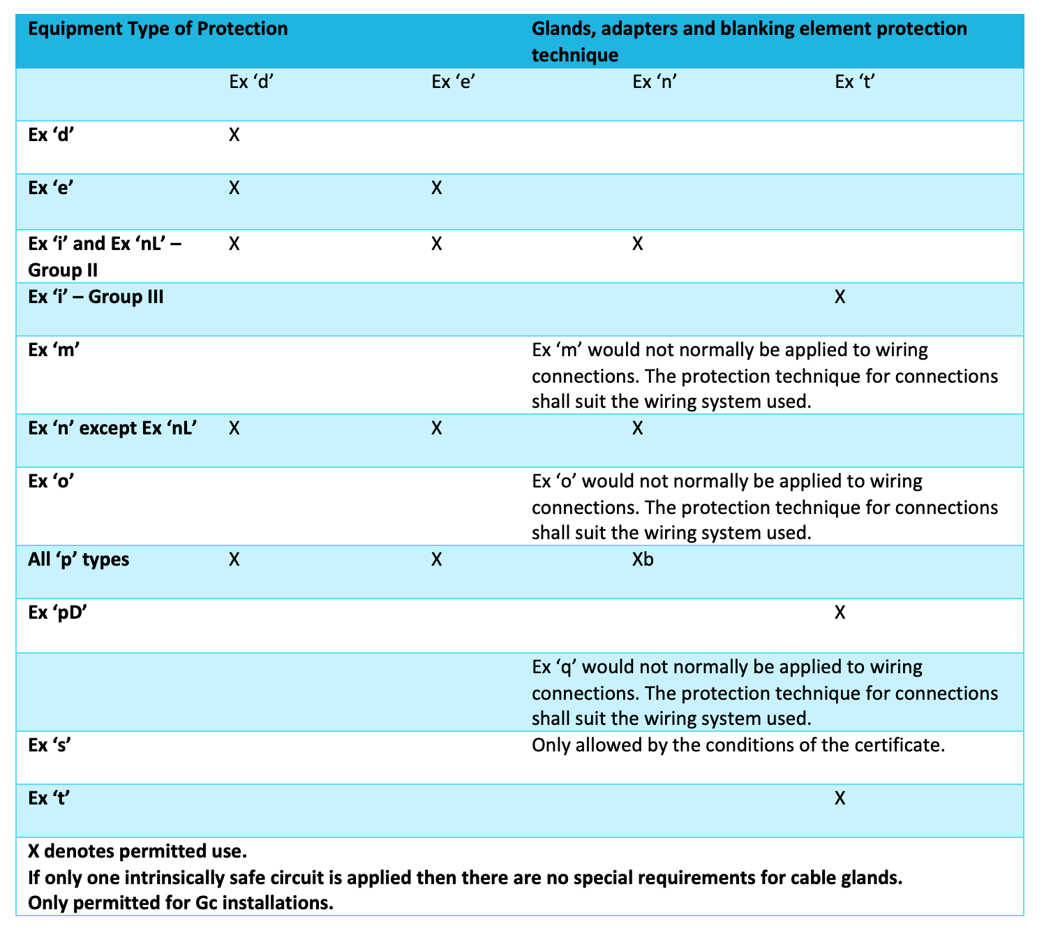
Cable glands and adapters shall be certified. They shall be selected in accordance with Table 9.
Table 9: Selection of glands, adapters and blanking elements
3.12.5 Glanding for Ex ‘d’ Equipment
i ) Glands
Where cable glands are used for direct entry into an Ex ‘d’ enclosure, Ex ‘d’ or Ex ‘de’ glands should be used. In certain situations a barrier gland is required to ensure internal explosion will not result in the failure of the cable at the exit point. See Section 4.5.4 for more detail.
However, some Ex ‘d’ equipment may be certified with an indirect entry Ex ‘e’ terminal box. In these cases Ex ‘e’ or Ex ‘d’ glands may be used.
ii) Cable Entry to an Ex ‘d’ Enclosure containing Ex ‘i’ Associated Equipment
All glands used for direct entry to an Ex ‘d’ enclosures have to be Ex ‘d’ certified. For indirect entry, glands suitable for the terminal box should be used.
iii) Non Gland Entry into Ex ‘d’ Enclosures
Cable entry methods not requiring Ex ‘d’ glands would use:
stopper boxes or other sealing chambers;
plugs and sockets where the sockets are certified as parts of the equipment;
cable entry devices included in the certification
3.12.6 Glanding for Ex ‘e’ Equipment
i) Glands
Glands used on new installations need to be certified against the appropriate IEC Standards as Ex ‘e or Ex ‘d’. Prior to January 2008, normal El W industrial glands were permitted in accordance with IEC 60079-14.
ii) MICC Cable
Where MICC cable is used, Ex ‘e’ certified pots are required to provide the required core separation.
iii) IP Sealing Washers
Glands entering unthreaded holes, threaded holes with less than 6 mm thread length or where the thread is not square with the gland seating surface, require an IP seal washer on the outside and a lock-nut on the inside. A star washer may be specified to be fitted on the inside of metal enclosures in order to ensure satisfactory earth continuity.
Earth Tags
Where an external earth tag washer is required, this is to be placed between the gland body metal and the seal washer. It should not be placed between the box and the seal washer.
3.12.7 Glanding for Ex ‘n’ or Ex ‘N’ Equipment
i) Glands
Prior to 2008, cable glanding methods followed conventional practices and did not require certified glands. However, as from January 2008, all new installations require the use of certified cable glands and adapters. While Ex’nR’ glands do exist, they are not widely available. Glands rated as Ex ‘d’, Ex “e’ may also be used.
ii ) IP Sealing Washers
Glands entering unthreaded holes, threaded holes with less than 6 mm thread length or where the threads are not square with the surface, require an IP seal washer on the outside and a lock-nut on the inside. A star-washer may be specified to be fitted on the inside of metal enclosures in order to ensure satisfactory earth continuity.
iii) Earth Tag Washers
Where an external earth tag washer js required, this is to be placed between the gland body metal and the seal washer. It should not be placed between the box and the seal washer.
3.12.8 Glands for Ex’i’ systems
Glands should be appropriate to the equipment protection type (see Table 9). If connecting cables for intrinsically safe equipment enter into an Ex ‘d’ enclosure, then Ex ‘d’ glands of a type to suit the cable and the type of entry are to be used.
3.13 Wiring systems
3.13.1 Cables
i) Conductor Materials
copper conductors may be used in any size required;
aluminium conductors are not permitted unless their cross-sectional area is at least 16 mm2 except in intrinsically safe systems.
ii) Power Cable Colours
The following colours for power cables became mandatory for all new cable from March 2006:
phase colour’s: brown, black, grey
neutral: blue
protective conductor: yellow/green.
Conductor Insulation
Normally thermoplastic or elastomeric material, but alternatively mineral insulation can be used. Refer to IEC 60079-14 for more details.
Wire Armouring
Armouring is not essential provided that cables are protected against mechanical damage. Galvanised steel wire is acceptable for use with multi-core cables. Screened Cables
Where the screening is used to minimise parasitic signal interference, it needs to be protected from mechanical damage.
Single Core Cable Armour
Single core cables shall be provided with non-magnetic armour. For offshore installations these are normally tinned copper or bronze wire braided. Those manufactured to BS 6724 and made from Aluminium only are not permitted offshore but may be used onshore.
3.13.2 Cable/Wire Marking and Numbering
All cables, cores and terminals shall be marked for identification purposes by permanent indelible methods. These details shall be documented.
3.13.3 Jointing
EEMUA Comment:
The following text is extracted from IEC 60079-14:2008. It was omitted from the current (2013) edition by mistake. The team responsible for the revision of the standard have ‘Accepted in principle’ that it should be re-instated in the next edition.
Cable runs in hazardous areas should, where practicable, be uninterrupted. Where discontinuities cannot be avoided, the joint, in addition to being mechanically, electrically and environmentally suitable for the situation, shall be:
made in an enclosure with a type of protection appropriate to the EPL requirements for the location, or providing the joint is not subject to mechanical stress, be ‘epoxy’ filled, compound-filled or sleeved with heatshrunk tubing or cold-shrunk tubing, in accordance with the manufacturer’s instructions.
Conductor connections, with the exception of those in flameproof conduit systems, intrinsically safe circuits and energy-limited circuits, shall be made only by means of compression connectors, secured screw connectors, welding or brazing. Soldering is permissible if the conductors being connected are held together by suitable mechanical means and then soldered, so there is no stress on the connection.
3.14 Marking Details
Equipment for use in explosive atmospheres will be marked in accordance with IEC 60079-0 with the following:
‘Ex’ followed by the type of protection e.g. ‘d’
Equipment group e.g. ‘IIC’
Temperature class e.g. ‘T3’
Explosion protection level e.g. ‘(3b’
Equipment conforming to the requirements of the AT EX Directives is additionally marked with the following: CE mark
Notified Body identification number e.g. 1 0123’;
‘Ex’ inside a hexagon;
Equipment group e.g. ‘IIC’; Category e.g. ‘2’; Gas/dust e.g.
3.14.1 Specific Conditions of Use X
The symbol “X” is sometimes placed after the certificate number. It is used to provide a means of identifying that essential information for the installation, use and maintenance of the equipment is contained within the certificate.
For more information, refer to relevant standards, EEMUA 186 - A Practitioner’s Handbook or the appropriate superior technical authority.
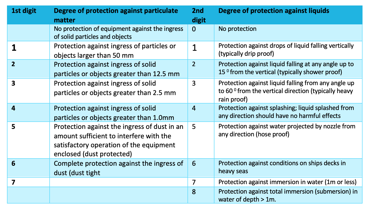
3.15 Ingress Protection
Prevention of particulate matter and water entering into the equipment is known as ingress protection and equipment is given an IP rating.
Deluge protection provides additional ingress protection when a large volume of water, such as from a fire-fighting supply, routinely cascades over the equipment.
Table 10: Ingress protection (IP) code (IEC 60529)
Most industrial cabling uses flexible armoured construction with Steel Wire Armour (SWA) or Braid Armour. Those cables require specific fixing mechanisms, glands, which retain the cable in a fixed, solid manner at the enclosure walls.
Several manufacturers produce a range of gland fittings and accessories for non-hazardous and hazardous industrial applications.
Two examples of types of Exd gland are shown below.
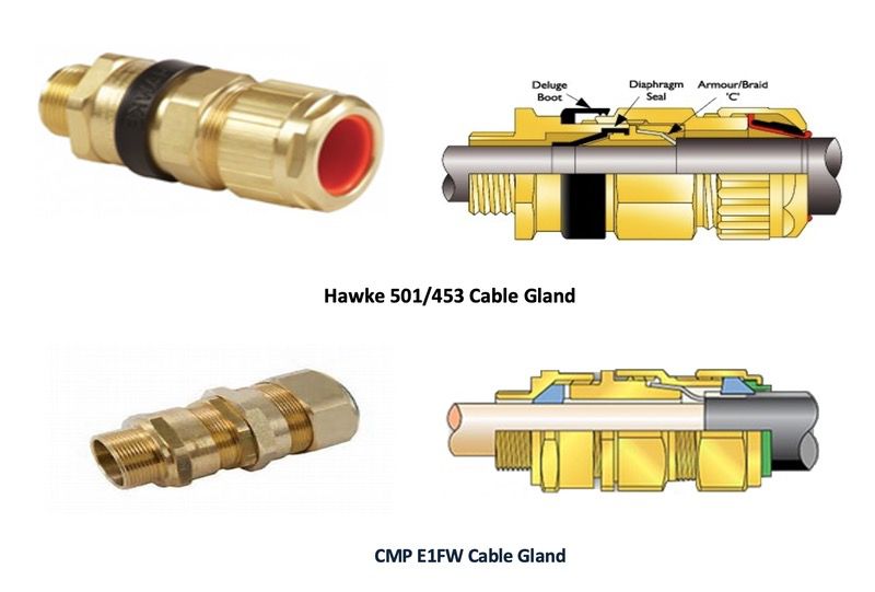
Your Trainer will now show a Hawke cable gland video clip of the 501/453 universal gland & the 501/653 RAC universal gland
The cable glands made for Exd enclosures have extra detail added to make them more suitable for use in a Zone 1 environment.
Additional features are:
- Double, internal gas seals used for internal and external cable sheaths.
- Flame paths in the body joints of the gland body
- Insertion thread for the enclosure fixing has more than 5 threads to meet IIB and IIC requirements.
An additional requirement for IIC enclosures is the use of a “barrier” gland when the enclosure has an internal volume of 2 litres, or more. Below are 2 examples of a barrier gland.
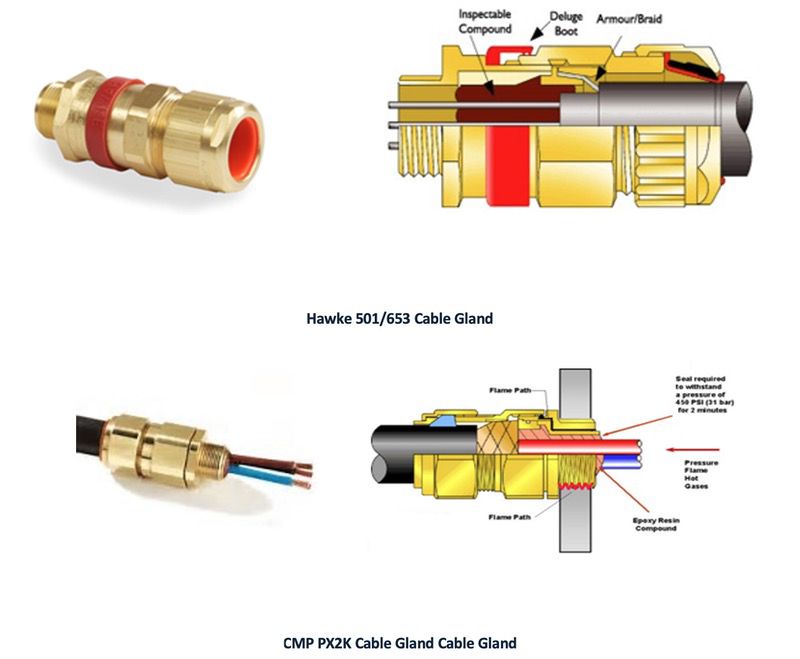
Space inside the cable gland is filled with a hard-setting compound, which is used to prevent hot gases escaping from a IIC gas explosion. Inside a 2.0 litre enclosure, the pressures involved in a IIC explosion could damage the cable insulation and force hot gases past the cable insulation and gland seals.
Different methods of cable entry into an Exd enclosure is shown below, Type IIC with screwed cover is illustrated:
The first enclosure in the above image illustrates indirect connection by way of an increased safety (Exe) enclosure. This allows external termination of the cable wires. Wire entry from Exe enclosure to Exd enclosure is sealed with a hard potting compound.
The second enclosure illustrates DIRECT connection using a SWA cable gland. Cable gland is typically threaded 20mm or 25mm.
Correct choice of Exd gland is important, as described above.
The third enclosure illustration shows a conduit pipe connection that is used commonly in North American installations. The conduit entry must be fitted with a stopping box, which is back-filled with hard setting compound.